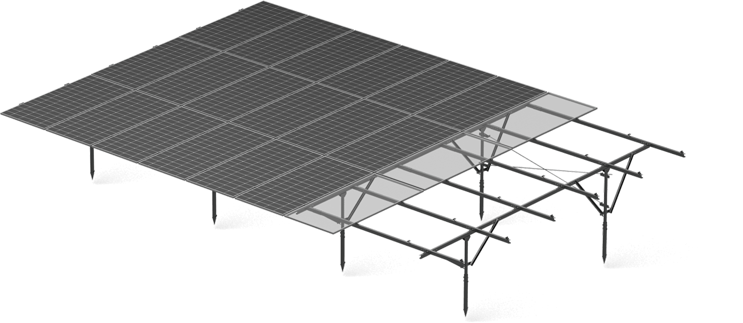
Navigating complex balance-of-system engineering requirements demands a precise understanding of the structural components that uphold large-scale photovoltaic arrays. Field personnel, procurement managers, and civil engineers must analyze structural terminology to ensure sub-ground profiles and above-ground racking interface seamlessly. Specifying a robust solar ground racking system allows commercial developers and installation teams to optimize physical load paths across variable topographies. Integrating specialized ground solutions engineered by primary fabricators like Antaisolar helps project teams align technical specifications with site-specific environmental criteria.
Structural Functions of Primary Purlins in Ground Racking Assemblies
Horizontal purlins serve as the primary structural bridge spanning between vertical support posts across a ground-mounted array. These structural channels transfer physical panel loads, wind shear, and snow accumulation directly into the foundation pile network. Profile geometry determines bending resistance along the longitudinal axis, allowing engineers to balance material weight against required span distances between support columns.
Selecting high-yield structural steel or heavy-duty aluminum purlins prevents structural sagging and localized buckling under heavy environmental loads. Cold-formed C-shaped and Z-shaped purlin profiles maximize section modulus efficiency while minimizing raw steel usage per megawatt. Using appropriately engineered structural members can help maintain the required frame stiffness across uneven terrain.
Rail Geometry and Load Transfer Dynamics in Fixed-Tilt Arrays
Support rails connect to the primary structural members and provide the mounting interface for photovoltaic modules, with their orientation determined by the system design. Advanced rail extrusions feature continuous internal channels designed to capture fastener heads and speed up module placement. Mechanical rigidity across these structural rails prevents excessive frame deflection that could otherwise induce micro-cracks in fragile silicon wafer cells during severe wind gusts.
Extruded aluminum rails offer favorable strength-to-weight ratios alongside natural atmospheric corrosion resistance in high-humidity environments. Galvanized steel or Zinc-Aluminum-Magnesium coated rails provide cost-effective alternatives for massive utility-scale fields requiring high structural stiffness. Precise mechanical engineering dictates rail profile height and wall thickness, ensuring secondary support frameworks absorb dynamic mechanical stress without experiencing plastic deformation over twenty-five years of service.
Module Attachment Mechanics: Mid Clamps and End Clamps
Fixing photovoltaic modules onto aluminum or steel racking profiles relies on specialized mechanical clamps engineered to deliver uniform clamping force. Mid clamps fit between adjacent PV modules, securing two panel frames simultaneously with a single threaded fastener assembly. End clamps secure the outer modules and are designed to transfer applicable lateral and uplift loads through the mounting interface.
Improper torque application or unsuitable clamp materials and designs can reduce the mechanical performance of the module-to-rail connection under wind loading. Modern clamping hardware incorporates integrated grounding pins or washer plates, establishing continuous electrical bonding across module frames and primary racking steel simultaneously. Utilizing standardized mounting hardware, including pre-assembled structural components where available, can simplify field assembly.
Pitch Angle Engineering and Seasonal Tilt Optimization
Determining the operational tilt angle represents a critical factor in maximizing annual photovoltaic energy yield per installed panel. Fixed-tilt racking systems use a static inclination angle selected to optimize solar irradiation received by the modules based on site-specific conditions. In northern latitudes or high-snow environments, steeper tilt angles facilitate passive snow shedding, preventing snow accumulation from shading active cells or imposing excessive dead loads.
Adjustable tilt configurations allow installation teams to modify array angles seasonally, shifting structural inclination to match solar elevation changes throughout the year. Setting accurate tilt parameters requires balancing aerodynamic uplift risks against power generation objectives. Steeper tilt angles increase wind pressure profiles along array rear faces, requiring heavier foundation piles, reinforced purlins, and stiffer structural joints to maintain overall mechanical equilibrium.
Ground Interfaces and Subsurface Foundation Dynamics
Anchoring structural purlins and vertical posts into subterranean strata demands evaluating soil density, frost depth, and corrosion risk. Driven steel H-piles provide rapid installation speeds in uniform soil conditions, transferring vertical down-forces and uplift loads into deep earth layers. Concrete pier foundations or cast-in-place piles offer structural stability in rocky terrain, loose soil conditions, or flood-prone locations where driven piles encounter subterranean obstruction.
Helical ground screws can provide suitable pull-out capacity in certain soil conditions when their design and installation are verified through site-specific engineering.Selecting the proper ground foundation interface protects structural integrity, preventing differential settling from twisting racking frames out of tolerance over time. Specifying high-integrity foundation components across the complete solar ground racking system ensures long-term operational resilience regardless of underlying geological constraints.
Component Integration and Long-Term Structural Reliability
Achieving smooth construction workflows depends on component compatibility across purlins, support rails, clamps, and foundation interfaces. Pre-assembled structural modules reduce job-site hardware counts, simplifying inventory logistics and minimizing installation errors during field construction. Standardized bolt channels, click-in clamping mechanisms, and pre-drilled connection plates enable field crews to execute swift structural assembly under tight project deadlines.
Verifying structural integrity requires comprehensive finite element analysis and physical mechanical testing of all load-bearing components. Working with primary manufacturing partners provides access to mill test reports, corrosion certifications, and wind tunnel validation data for every structural component. Understanding core structural terminology enables EPC contractors, procurement teams, and developers to select robust, code-compliant ground racking infrastructure engineered for maximum multi-decade asset performance.
Conclusion
Evaluating the core mechanical components—including purlins, support rails, mounting clamps, and tilt structures—enables engineering teams to design reliable photovoltaic arrays. Understanding how these structural elements interact simplifies procurement workflows, accelerates field installation, and safeguards utility assets against harsh environmental exposure. Collaborating with trusted manufacturing partners like Antaisolar provides developers, EPC contractors, and distributors with fully integrated ground mounting hardware designed to support long-term structural performance over their intended service life.
